
Last updated on 06th Nov 2025| 12754
- Electric Vehicle Drawing
- Importance of EV Diagrams
- EV System Architecture
- Battery Pack Design
- Powertrain Layout
- Charging Circuit Diagram
- Regenerative Braking Diagram
- Cooling System Layout
- Controller and BMS Schematics
- Safety and Isolation Diagram
- Tools for Creating EV Drawings
- Conclusion
Electric Vehicle Drawing
Electric vehicles (EVs) are revolutionizing the way we think about transportation. They offer a cleaner, more efficient alternative to traditional internal combustion engine vehicles, producing zero tailpipe emissions and relying on electricity rather than fossil fuels. As EV technology continues to advance, it becomes increasingly important to understand the components and systems that make up these complex machines. To explore how intelligent systems enhance electric vehicle innovation through predictive diagnostics, smart energy management, and adaptive control strategies, explore Artificial Intelligence Training a hands-on course that covers machine learning, embedded AI, and sustainable mobility applications for next-generation automotive engineering. One of the best ways to visualize and comprehend EV systems is through detailed diagrams. These diagrams serve as blueprints that illustrate how various components work together, facilitating design, development, maintenance, and education. In this guide, we will explore the key EV diagrams, their significance, system architecture, and the tools used to create them.
Importance of EV Diagrams
Electric Vehicle Drawing is important tools that visually show the electrical and mechanical systems in electric vehicles. They provide clear benefits to many groups, including engineers, technicians, educators, and regulatory bodies. For engineers who design and develop electric vehicles, these diagrams are very helpful. They allow engineers to see where components go and how systems connect, making it easier to visualize the interaction between motors, controllers, and battery systems. To explore how different motors operate and how their speed is managed in EVs, explore Motor Types and Their Speed a comprehensive guide that explains induction motors, permanent magnet motors, switched reluctance motors, and the control strategies that optimize performance and efficiency. Clear schematics during the design phase help ensure the vehicle operates safely and efficiently by guiding the planning of wiring, component connections, and effective use of space. Additionally, detailed circuit diagrams and layouts are crucial for service technicians when troubleshooting and maintaining vehicles. These diagrams help with diagnosing problems and replacing faulty parts. They also make the repair process more efficient, which reduces vehicle downtime and ensures proper service. In educational and training settings, Electric Vehicle Drawing is essential for breaking down complex systems. They help students and trainees understand how different components, like the battery, motor, and powertrain, interact with each other.
Ready to Get Certified in Artificial Intelligence ? Explore the Program Now Artificial Intelligence Online Training Offered By ACTE Right Now!
EV System Architecture
The architecture of an electric vehicle comprises multiple interdependent subsystems that coordinate to deliver efficient and reliable performance. A typical EV system architecture diagram includes the battery pack, motor, controller, charging unit, and communication interfaces, all working together seamlessly. To understand how these subsystems are integrated and managed through intelligent control, explore Embedded Systems in Electric Vehicle a comprehensive guide that explains microcontroller functions, real-time monitoring, signal processing, and the critical role embedded systems play in optimizing EV performance and safety.
- Battery Pack: The energy source for the vehicle.
- Electric Motor: Converts electrical energy into mechanical energy.
- Inverter: Converts DC from the battery into AC for the motor.
- DC-DC Converter: Steps down high-voltage DC to lower-voltage DC for auxiliary systems.
- Onboard Charger: Manages charging from external power sources.
- Vehicle Control Unit (VCU): Central unit that manages communication and control across systems.
- Transmission and Differential: Transfers torque from the motor to the wheels.
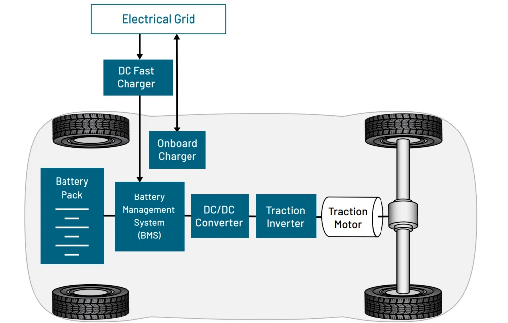
This architectural layout helps engineers design and evaluate overall system functionality and interactions.
To Explore Artificial Intelligence in Depth, Check Out Our Comprehensive Artificial Intelligence Online Training To Gain Insights From Our Experts!
Battery Pack Design
The battery pack is a critical component in EVs, responsible for storing and supplying energy to the motor and other electrical systems. A comprehensive battery pack design diagram includes multiple subsystems such as cell modules, cooling systems, and battery management units. To explore how intelligent systems optimize battery design through predictive diagnostics, smart energy distribution, and adaptive thermal management, explore Artificial Intelligence Training a hands-on course that covers machine learning, embedded AI, and advanced energy solutions for next-generation electric vehicles.
- Cell Arrangement: Cells are arranged in series and parallel to achieve desired voltage and capacity.
- Battery Modules and Pack: Groups of cells are assembled into modules and then into a complete pack.
- Battery Management System (BMS): Monitors and controls parameters like voltage, current, and temperature.
- Cooling System: Liquid or air cooling mechanisms to maintain optimal temperatures.
- Safety Systems: Fuses, relays, thermal sensors, and isolation monitoring devices.
- Enclosure and Mounting: Structural aspects of how the battery pack is integrated into the vehicle.
Efficient battery pack design enhances energy density, performance, and longevity while ensuring safety.
Powertrain Layout
The powertrain of an electric vehicle (EV) consists of various parts that efficiently deliver power from the battery to the wheels. A typical powertrain layout diagram shows several key elements. It starts with the Electric Drive Unit (EDU), which combines the motor, inverter, and gear system into one unit. Next, the gearbox or direct drive system is crucial for transferring rotational energy, either with or without gear reduction, allowing for better performance. To understand how these components scale across multiple vehicles and are optimized for operational efficiency, explore EV Fleet Management a comprehensive guide that explains fleet electrification strategies, charging coordination, maintenance scheduling, and the role of data-driven management in reducing costs and improving sustainability. The powertrain also has axles and a differential, which are vital for distributing power to the drive wheels. This ensures smooth and responsive handling. Additionally, the power flow path shows how energy moves from the battery to the motor and then to the wheels. This layout helps engineers visualize the mechanics involved. It also improves efficiency, torque delivery, and packaging of the drivetrain, boosting the overall performance of the electric vehicle.

Develop Your Skills with Artificial Intelligence Training
Weekday / Weekend BatchesSee Batch DetailsCharging Circuit Diagram
Charging infrastructure is key to making electric vehicles (EVs) easier to use. Understanding its main parts is important for effective system design. The charging port is central to the process; it connects to the power grid and lets energy flow into the vehicle. The onboard charger (OBC) is crucial in this system because it changes alternating current (AC) to direct current (DC) and controls the battery’s charge levels. This ensures the vehicle performs well and lasts longer by maintaining optimal charging cycles and protecting battery health. To explore how such components are applied in real-world innovations and student-led experiments, explore Electric Vehicle Projects a comprehensive guide that showcases practical EV systems, project ideas, component integration, and the engineering approaches that bring electric mobility concepts to life. For faster charging, external chargers, such as DC fast charging systems like CCS and CHAdeMO, deliver the power needed for quick recharges. Communication interfaces are essential too. They allow data exchange between the vehicle and the charger, which is necessary for monitoring and managing the charging session. Protection circuits also play a vital role in the safety of the charging system. These circuits have mechanisms for surge protection, overvoltage, undervoltage, and ground fault detection. All of these help prevent harm to the vehicle and the charging equipment. Lastly, connector types differ by region and standard, with options like Type 1, Type 2, and GB/T serving various markets. Together, these elements, shown in charging circuit diagrams, are important for designing charging systems that are safe, efficient, and compatible with a range of vehicles.
Looking to Master Machine Learning? Discover the Artificial Intelligence Expert Masters Program Training Course Available at ACTE Now!
Regenerative Braking Diagram
Regenerative braking is a key feature of EVs that recovers energy during deceleration. The diagram includes:
- Motor as Generator: During braking, the motor operates in reverse to convert kinetic energy into electrical energy.
- Inverter Operation: Redirects current back into the battery.
- BMS Integration: Ensures safe recharging of the battery.
- Brake Blending: Coordinates regenerative braking with friction brakes for seamless deceleration.
These diagrams are useful in optimizing energy recovery, reducing brake wear, and extending vehicle range.
Cooling System Layout
Effective thermal management ensures the longevity and safety of EV components. A cooling system layout diagram includes radiators, coolant pumps, heat exchangers, and control sensors that work together to regulate temperature. These systems are closely tied to the controller, which manages power flow and ensures that thermal limits are not exceeded during operation. To explore how controllers integrate with cooling and other subsystems, explore Electric Vehicle (EV) Controller a comprehensive guide that explains controller architecture, signal processing, thermal coordination, and the critical role controllers play in optimizing EV performance and safety.
- Coolant Flow Paths: Routes for coolant through batteries, motors, and inverters.
- Pumps and Valves: Regulate flow based on temperature feedback.
- Heat Exchangers: Remove heat using air or liquid cooling.
- Temperature Sensors: Monitor system temperatures in real-time.
- Fans and Radiators: Enhance heat dissipation.
An optimized cooling system prevents thermal runaway, maintains performance, and prolongs component life.
Preparing for Artificial Intelligence Job Interviews? Have a Look at Our Blog on Artificial Intelligence Interview Questions and Answers To Ace Your Interview!
Controller and BMS Schematics
The controller and Battery Management System (BMS) are crucial for the safe and efficient operation of electric vehicles (EVs). The schematics of these systems usually include several key elements that work together to improve performance. At the center, Central Processing Units (CPUs) manage the logic and control algorithms, ensuring that the system runs smoothly.

Current and voltage sensors continuously monitor operating conditions and provide real-time data that is essential for performance assessment. Temperature sensors are also important; they help ensure that all components work within safe limits to prevent overheating and potential failures. In addition, communication interfaces like CAN, LIN, SPI, and I2C protocols enable effective communication between different system components, allowing for coordinated operations. Power supply circuits are included to regulate internal voltages and ensure that all components receive the right power levels for their operation.
Safety and Isolation Diagram
High-voltage electric vehicle (EV) systems pose significant safety challenges, requiring strict safety protocols. A key part of these protocols is the safety and isolation diagram, which includes several critical components designed to reduce risks. Insulation Monitoring Devices (IMDs) are crucial as they monitor insulation resistance continuously to ensure safe operation. In an emergency, high-voltage disconnects allow for immediate power shutdown, improving safety. These protective mechanisms are part of the broader ecosystem that ensures reliability in modern EVs. To explore how these safety systems integrate with charging infrastructure and user convenience, explore Electric Vehicle Charging a comprehensive guide that explains charging methods, connector standards, safety protocols, and the innovations shaping the future of EV charging networks. Ground fault detection systems are also important; they help prevent dangerous currents that could cause serious accidents. Fuses and circuit breakers provide additional protection against overcurrent conditions, while contactors and relays act as electrically controlled switches for effective load management. To enhance safety further, shielding and enclosures prevent electromagnetic interference (EMI) and protect against physical damage. Including these elements in safety diagrams is not just recommended, it is required for confirming the safety of high-voltage systems during their design, certification, and operational phases, ensuring a thorough approach to risk management in this evolving technology field.
Tools for Creating EV Drawings
Creating precise Electric Vehicle Drawing requires specialized software tools. Here are some of the most widely used, CAD platforms for mechanical design, simulation software for thermal and electrical analysis, and embedded system modeling tools for control integration. These solutions help engineers visualize how motors, batteries, and controllers interact within the drivetrain. To explore how these components come together in real-world applications, explore EV Powertrain a comprehensive guide that explains drivetrain architecture, motor-battery coordination, efficiency optimization, and the engineering strategies that define modern electric vehicles.
- AutoCAD Electrical: Ideal for creating complex electrical schematics and control systems.
- SolidWorks Electrical: Offers integrated mechanical and electrical design for collaborative development.
- EPLAN Electric P8: A high-end solution for designing electrical and fluid power systems.
- Altium Designer: Widely used for PCB design, especially for control and BMS hardware.
- MATLAB/Simulink: Useful for simulating EV systems and validating control logic.
- Fusion 360: Combines CAD, CAM, and CAE for full-system 3D modeling and simulation.
- KiCad and Eagle: Open-source tools for creating PCB layouts and circuit diagrams.
The choice of tool depends on the project scope, system complexity, and team expertise.
Conclusion
Electric Vehicle Drawing is indispensable in the design, development, maintenance, and education of electric vehicles. From system architecture and battery design to cooling layouts and safety schematics, each type of diagram serves a unique purpose in ensuring the vehicle’s efficiency, performance, and safety. To explore how intelligent systems enhance these engineering diagrams through predictive modeling, smart energy distribution, and adaptive safety controls, explore Artificial Intelligence Training a hands-on course that covers machine learning, embedded AI, and advanced automotive engineering applications for next-generation electric vehicles. These diagrams not only streamline engineering processes but also facilitate learning and regulatory compliance. As electric vehicle technology continues to evolve, the role of detailed and accurate system diagrams will become even more significant. Professionals equipped with the knowledge and tools to create and interpret these diagrams will be at the forefront of innovation in sustainable transportation.