Last updated on 15th Jul 2020| 3184
- Function Point Analysis is a method of estimating the size of a project by considering the input and output elements that are in the project and consolidates each type of operation into data or transaction function. The size of projects used to be computed using the KLOC (Kilo Lines of Code), but could not be applied before the project was completed, as the prediction models were far from being accurate, but the concept had similarities to FPA as observed by Allan J. Albrecht, the inventor of FPA. The FPA methodology for sizing software was devised by him at IBM. The introduction of FP Counting practice helps to ascertain the size of the project by considering all the variables in the equation to deliver the function point count, and provided better estimates than those computed by analogy and user experience.
- The Function Point Analysis estimation methodology validates the individual elements and the related groups to arrive at a complexity level of high, medium and low and assigns a function point count for each subset. There are five basic function types Internal Logical Files (ILF), External Interface Files (EIF) in data functions and External Inputs (EI), External Output (EO) and External Query (EQ) in transaction functions. The elementary variables in functions are denoted as Data Element Type (DET).
- The functional complexity is computed as the total number of user identifiable groups that exists within DETs and is termed as Record Element Type (RET) in Data Functions and all referenced file types are counted as File Type Records (FTR) in Transactions Functions. A corresponding matrix holds the reference function point values for all function types namely the ILF, EIF, EI, EO and EQ, with respect to the range of DET and RET/FTR in each function.
- The total sum of the high, medium and low count of all operations is the unadjusted function point count. There are 14 General System Characteristics used to ascertain the Adjusted Function point count. The GSC computed in each project is called the Value Adjustment Factor. This is used to calculate the complexity of environment, task and language and tweak the final count for the particular environment.
- The Project count can be broadly classified into three types as defined in the Function Point Manual by David H. Longstreet.
Development Function Point Count:
Function Points can be counted at all phases of a development project from requirements leading up to implementation. This type of count is associated with new development work and may include the prototypes, which may have been required as a temporary solution, which supports the conversion effort. This type of count is called a baseline function point count.
Enhancement Function Point Count:
It is common to enhance software after it has been placed into production. This type of function point count tries to size enhancement projects and is counted as the sum of all added, changed or deleted function points in the application. By tracking enhancement size and associated costs, a historical database for your organization can be built. Additionally, it is important to understand how a development project changes over time.
Application Function Point Count:
Application counts are calculated as the function points delivered, and exclude any conversion effort (prototypes or temporary solutions) and existing functionality that may have existed.
To perform function point analysis, we have to first define the boundary of the application. A boundary is used to define what is internal to the application and what component or interfaces are external to the application. This distinction is important and once the boundary is established, it remains constant throughout the lifetime of the application, and is used as reference for all future estimations. The boundary is a user perspective based on the understanding of the system and related environment.
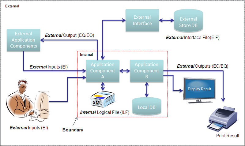
To perform function point analysis the functional categories are derived into two basic types, the ”data functions” and ”transaction functions”.
Data Functions
Data functions relate to the actions of storing and retrieving data in both local files or databases and external to the application through remote interfaces, associated middleware or outside the boundary of the application concerned.
IFPUG: Internal Logical File (ILF)
User recognizable group of logically related data or control information maintained within the boundary of the application being measured. The primary intent of an ILF is to hold data maintained through one or more elementary processes of the application being counted.
Simple Definition
The entity model to which data is persisted (stored) by the application should be within its boundary, which may be the local database, file data source or any other type of persistence mechanism. Data is organized into groups and subgroups. The subgroups are more commonly related to tables in a database. A group is a collection of tables that has affinity to a particular entity, department, location or any other user identifiable selection criteria like Customer Records or Orders. The data is maintained in the ILFs through an elementary process, which is (CRUD) Create, Read, Update, and Delete operation from within the application boundary and is referenced by an Add, Update, Delete transaction function. Control information may be passed as an indicator of the process to be performed.
Counting Rules
The group of data or control information is logical and user defined. The group of data is maintained through an elementary process within the application boundary being counted.
Identifiers
Validate any CRUD operation performed on a database, table, file or component including in memory caching within the boundary of the application.
IFPUG: External Interface File (EIF)
An external interface file (EIF) is a user identifiable group of logically related data or control information referenced by the application, but maintained within the boundary of another application. The primary intent of an EIF is to hold data referenced through one or more elementary processes within the boundary of the application counted. This means an EIF counted for an application must be in an ILF in another application.
Simple Definition
Data transmitted or persisted outside the application boundary, which can be accessed through the use of a remote application interface, a remote server, or data which may be maintained by another application and managed through remote interface. Each of the fields required may be individually counted and reference keys and structures may also be counted. The nature of storage and retrieval alter the form, such as into key value pairs, or serialized to a string, or exchanged as XML data. The groups and subgroups are derived from the logical structure and not data in its physical state.
Counting Rules
- Count a DET for each unique user recognizable, non-repeated field maintained in or retrieved from the ILF or EIF through the execution of an elementary process.
- Count only those DETs being used by the application being measured when two or more applications maintain and/or reference the same data function.
- Review related attributes to determine if they are grouped and counted as a single DET or whether they are counted as multiple DETs; grouping will depend on how the external process use the attributes within the application
- Count a DET for each attribute required by the user to establish a relationship with another ILF or EIF.
Identifiers
Any operation invoked through a web services interface, or remote application interface through some middle-ware technology or remote access through various protocols. The data is stored outside the boundary in another system typically in another application server, content management system or file server but referenced and used by the application concerned.
Transaction Functions
Transaction functions relate to read/write operations performed on the data. The transaction functions will read or write data from and to an ILF or EIF. There are three basic types of Transaction functions which comprises External Input, External Inquiry and External Output.
IFPUG: External Input (EI)
An external input (EI) is an elementary process that processes data or control information that comes from outside the application boundary. The primary intent of an EI is to maintain one or more ILFs and/or to alter the behavior of the system. Data entering the application boundary either by user input, data feed or an external application invocation.
Simple Definition
It denotes any data input screen or operation that is used to perform a CRUD operation on the ILF (database or persistent storage). This data received has to be stored to the database as tables or to files or some persistent storage mechanism and links to the corresponding ILF. It should alter the behavior by going from input data state to an updated data state.
Counting Rules
- Count one FTR for every read operation from ILF within the boundary or one per EIF file. Count one FTR for every write operation to an ILF within the boundary of the application.
- Only count the same ILF once for both read and write operations.
Identifiers
User provides data in an online application form, selecting options, choices, inputs text, uploads files or feeds data into the system. An external application sends data to be stored/processed or both. Receive data from external sources as stream feeds at intervals. Receive a device event such as alarms or triggers with relevant data to be processed.
IFPUG: External Inquiry (EQ)
An elementary process that sends data or control information outside the boundary. The primary intent of an external inquiry is to present information to the user through the retrieval of data or control information. The processing logic contains no mathematical formula or calculations, and creates no derived data. No ILF is maintained during the processing, nor is the behavior of the system altered.
Simple Definition
Denotes a simple data read operation, where information is retrieved or data is sent outside the boundary, which may simply be a display devices such as a PC monitor or information sent in response to a remote procedure call from another application outside the boundary. There may be some operations leading to the output which makes EQ and EO have both input and output parameters.
Counting Rules
- Sends data or control information external to the application’s boundary.
- For the identified external process, one of the following must apply
- Processing logic is unique from the processing logic performed by other EQs for the application.
- The set of data elements identified are different from other EQs in the application.
- The ILFs or EIFs referenced are different from files referenced by other EQs in the application.
Identifiers
- Data that is fetched from the database displayed as a result of some user action.
- Data which may be sent to external devices such as printers or other devices.
- Data which is sent to other external applications outside the application boundary.
IFPUG: External Output (EO)
An elementary process that sends data or control information sent outside the application’s boundary and includes additional processing beyond that of an external inquiry. The primary intent of an external output is to present information to a user through processing logic other than or in addition to the retrieval of data or control information. The processing logic must contain at least one mathematical formula or calculation, create derived data, maintain one or more ILFs, and/or alter the behavior of the system.
Simple Definition
This is a data read operation and the result may be displayed, printed, transmitted to an external device or application outside the application boundary and is similar in all respects to EQ. The control information may be additional data that may include information on how the data may be processed. The main difference of an EO from an EQ is that it may contain some mathematical equation, calculation of sum, average, count or other manipulation of data, or may create additional derived fields such as totals, subtotals, calculation of final cost and may also update the ILF to reflect the computed sum.
Counting Rules
- Sends data or control information external to the application’s boundary.
- For the identified external process, one of the three conditions must apply
- Processing logic is unique from the processing logic performed by other EOs for the application.
- The set of data elements identified are different from other EOs in the application.
- The ILFs or EIFs referenced are different from files referenced by other EOs in the application.
Identifiers
Data is fetched from the data source (ILF) and some additional logic is applied to transform the data. This may result in creation of new fields which may be the outcome of some mathematical calculations and also may be saved after the information is computed back to the data source.
Counting Function Points
IFPUG: Data Element Type (DET)
A DET is a unique user recognizable, non-recursive field. A DET is information that is dynamic and not static. A dynamic field is read from a file or created from DET’s contained in a FTR. Additionally, a DET can invoke transactions or can be additional information regarding transactions. If a DET is recursive then only the first occurrence of the DET is considered not every occurrence.
Simple Definition
Data element types are the granular elements or fields collected from each of the transaction and data functions. These are the attributes contained in the tables, fields in UI forms, parameters passed in application calls. It may be data that is unique and user recognizable, for a data table we may reference the unique column headers, for form elements we count each of the form fields. Only the first unique instance is counted even if tables or records are repeated. By assessing the DETs in relation to the RETs in data function or FTRs in transaction function we derive the complexity and arrive at the unadjusted function point count. Screen elements that are static like system time or page counters are not counted as DETs. For every application, any one-action link to submit the form contents will also be counted as a DET.
Counting Rules
- Count one DET for each data input field, error messages, calculated values & a single action button or link leading to submission for External Inputs.
- For External Outputs count each Data Field on a Report, calculated values, error messages, and column headings that are read from an ILF.
- Count one DET for EQ and EO for both input side and output sides. The input side which may be field used for selection or search, and output side is displayed on a screen.
Identifiers

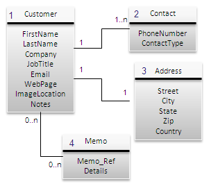
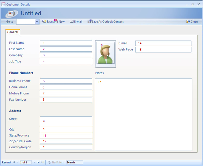
In the data entry screen shown above, we have counted 18 DET elements, of which the last element is the action button which can trigger an action. Only a single action button is computed in the equation. This transaction may be titled as “Process and Store Customer Details” and will contain 18 DETs and 1 FTR, the Customer group.
IFPUG: Record Element Type (RET) A RET is a user recognizable sub group of data elements within an ILF or an EIF. The child information is a subset of the parent information.
Simple Definition
Record Element Type (RET) is the logical sub group of elements, which may exist in the ILF, and could be related tables in a database or relations of a parent cluster. An entity may consist of several closely related tables or composite relations, for which one RET is counted, for other relational tables where they are related by common key such as in an association relation, count one RET for each referenced table, file type or entity. The complexity measure for a given function is weighed by counting the number of RETs identified in the DETs.
Counting Rules
- Count one RET for each table in a user identifiable group in ILF or EIF.
- Count one RET for each sub-group in a parent group.
Identifiers
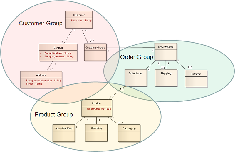
To identify RETs, we must first identify the respective user identifiable groups such as customers, orders, products. In each group there will be sub groups or related tables within the group. We count the number of subgroups in each group to list the number of RETs we are dealing with in a particular function, and count one RET for all the related tables from other groups which are referenced.

Get Advanced Blockchain Certification Course to Become An Blockchain Developer
Weekday / Weekend BatchesSee Batch DetailsIFPUG: File Type Referenced (FTR) A FTR is a file type referenced by a transaction. An FTR must also be an internal logical file or external interface file.
Simple Definition
File Type Referenced are logical groups either local storage or remote identified in a Transaction function. They are logical groups of data which must either be identified as an ILF or EIF.
Counting Rules
Count one FTR for each ILF or EIF in the transaction function.
Identifiers
Identify all the ILFs and EIFs in an application, and follow the process steps in a transaction function and count each unique reference to the EIF or ILF.
Reuse FP
It is important to denote the functional reuse that may exist within a project. There are two types of Reuse implemented in general, the functional reuse is used with each data and transaction function to denote the percentage of reuse in the given function, this is not a part of the standard IFPUG practice and is used only in progressive function point estimation. There may not be sufficient time in estimating the size of reusable modules when they are large complex libraries, or may not be available in certain COTS products when they are designed as a black box, for such instances, the weighted reuse percentage is based on user experience and analogy. A 0% reuse represents 100% new software build, any percentage denoted shows the total amount of reusable components available to the application for integration.
Reuse % = Reusable FP Count/Total FP Count
The second method of reuse is calculated with Adaption Adjustment Factor (AAF) was presented in an IFPUG conference to calculate reuse with respect to integration of an entire application or component as a whole for any project. It takes into consideration three factors Design Modification (DM), Code Modification (CM), Integration & Testing (I&T).
AAF = .4DM +.3CM +.3I &T
Steps in Calculation of Reuse count
- Calculate FP count of Reusable components. (100FP)
- Determine the percentage of Development Effort. (50%)
- Determine the percentage of Coding Effort. (25%)
- Determine the Testing & Integration Effort. (75%)
- * Calculate Adoption Adjustment Factor
- AAF = (0.4 x0.25)+(0.3×0.50)+(0.3×0.50)
- AAF = .1 + 0.15 + .15
- AAF = .4
- Calculate Reuse
- Reuse = FP Count of Reusable component x AAF
- Reuse = 100 x .4
- Reuse = 40FP
Unadjusted Function Point Count
Unadjusted function points refer to total counted FPs in a project. The FP estimation begins after all data and transaction functions are keyed in. The function point value for each Data and Transaction function is identified for operations Added, Changed and Deleted functions that are in a given User Story or Use Case. The function point count is based on the number of DETs and RETs/FTRs in the matching row and column of the Function Point Reference Matrix. The FP Reference Card provide value ranges for Low, Medium and High complexity transaction FP count based on the DETs and RETs present in a Data function or the DETs and FTRs in a transaction function.
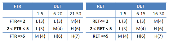
The FP value table is the IFPUG reference card and used for calculating the FP Count of ILFs and EIFs in Data Transactions. There are 3 ranges for DETs, and RETs. Based on each of the Low, Medium and High categories, a specific FP value is provided for data and transaction functions. This forms the basis of FP count determination. The total count derived from all the data and transaction functions listed in the project as the Unadjusted Function Point value.
Adjusted Function Point Count
The complexity factor can influence the final project count by +35%/-35%. The final count is termed as the adjusted function point count.
Value Adjustment Factors are used to derive the final adjusted function point count of an application. It uses 14 General System Characteristics (GSC) to identify the total complexity factor for the application and are classified into the following categories:
- Data communications
- Distributed data processing
- Performance
- Heavily used configuration
- Transaction rate
- On-Line data entry
- End-user efficiency
- On-Line update
- Complex processing
- Reusability
- Installation ease
- Operational ease
- Multiple sites
- Facilitate change
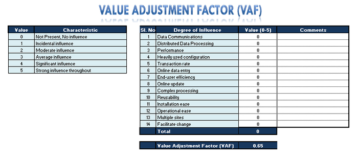
For each of the GSC a rating of 0 to 5 can be provided which represents
- 0=Not present, or no influence
- 1= Incidental influence
- 2=Moderate influence
- 3=Average influence
- 4= Significant influence
- 5=Strong influence throughout
Once all the details of the project are provided, and the VAF is calculated, the Unadjusted FP is multiplied with the VAF factor to arrive at the Adjusted Function Point Value. The VAF can influence the project by increasing or decreasing the unadjusted FP count by 35%. This ensures that the complexity of the environment is factored into the project.
PROGRESSIVE FUNCTION POINT ANALYSIS
Progressive function points were derived for greater accuracy in the estimation of Function Points using the same FPA principles but attempts to improve on the actual Function point count based on elementary inputs, outputs and integrated process flows within the respective functions. Progressive function points are better suited for application that may have the following characteristics
- Consistent measures above IFPUG FP Reference range.
- Complex operations other than standard CRUD functionality.
- Integration of Reuse within functions.
- Greater Accuracy of Cost & Schedule Index.
- Greater Clarity and Accountability into costing of applications.
- Passing external reviews such as CPMG Audits.
- Integration of new languages and programming tools.
The elementary process steps of a function are derived from a sequence diagram or activity diagram. The sequence diagram may contain the depiction of both data and transaction functions.
Definition
Progressive Function Point Analysis is a method of estimating the size of a project by considering the input and output elements and the elementary process steps that are in the project. The estimation methodology validates the elementary input, output elements and elementary processes with respect to their related groups and collaborations. There are five basic function types Internal Logical Files(ILF), External Interface Files (EIF) in data functions and External Inputs (EI), External Output (EO) and External Query (EQ) in transaction
Progressive FPA: Integrated Process Flow (IPF)
Integrated process flow comprises of the user recognizable, elementary non-repetitive process steps, which are present in both data and transaction functions and may include one or more process steps within respective logical groups inside the boundary of the application and may include references to External Component Interfaces to reuse functionality in other application(s) and to accomplish a desired outcome.
Progressive FPA: External Component Interfaces (ECI)
External Component Interfaces are integrated process flows of other applications. ECI are external functions referenced by applications to implement some desired functionality by reusing functions outside their application boundary.
Progressive FPA: Process Element Type (PET)
Process Element Type is a user recognizable elementary computational process steps to manage, process or present data and control information within each data or transaction function. The primary intent is to accomplish a desired behavior through one or more activities within the application boundary, which is unique to the application and may include calls and external references to other External Component Interfaces (ECI) outside the application boundary.
Simple Definition
The list of operations or activities performed by a function or multiple group of functions is termed the process steps and used to deliver a desired result or business function as stated in the use case or user story. They are computationally relevant when they perform some action that delivers a unique outcome in terms of mathematical operation, logical operation, calculation or business function that may influence a change in its state. Ideally, each function will perform one unique action and follow the single responsibility principle, so there is better readability in the code, as it implements Clean Code practices. The parent process may further invoke multiple function calls to obtain the desired behavior or result where each function follows a single responsibility pattern. Count every process step performed within the boundary of the application and count only one-step for each external call or reference to External Component Interfaces even if all process steps are outside the boundary of the application. The External Component Interfaces are references to external application processes counted as PETs within their own application boundary hence may denote reuse. The process flows may be presented in UML through activity diagrams or sequence diagrams to adhere to a well-articulated architecture blueprint and thus both UML diagrams and wireframes may be used to add clarity to design and implementation. It is advisable to list the steps involved in each process flow for validation purposes.
Counting Rules
- Count one process step for each computational operation performed by the function.
- Count one process step for each child function referenced by the parent function to accomplish a computational task.
- Count one process step for any operation or group of computational operations processed outside the boundary of the application in a single external reference call to obtain the desired result.
Identifiers
Identify list of activities; try to identify each computational process steps within each function type. Each operation or activity should define a separate function to follow the single responsibility pattern. Decisions are not counted rather the function flow of all outcomes are counted. Identify both internal function calls and external references to any other components and separate the ECI from the process flow, which may include reusable components or utilities. Identify the functions performed inside the boundary of the application and count one-step for each delegated operation.
Progressive FPA: Logical Collaboration Segments (LCS)
Logical collaboration segments are unique user recognizable logical groups or participants that may exist both within the boundary of the application for each data or transaction function, and relate to ECI with external participants as separate swim lanes which are outside the boundary of the application. LCS are depicted as swim lanes in BPM and can also be visualized using activity diagrams in UML.
Simple Definition
A functional flow leads to many process steps and traverses through one or more logical groups, participants or segments within the boundary of the application. Additionally each External Component Interfaces is counted as one group.
Counting Rules
- Count one logical collaboration segment for each user identified logical group, participant or segment.
- Count one logical collaboration segment for each unique External Component Interface in the process flow.
Identifiers
“FPA PET”)
Process flows are divided into many logical groups or swim lanes. Trace the function calls within the application boundary for unique operational sub tasks.